More power – more production
The NPK Powerbooster can be explained in 4 steps, as described above. As soon as the jaws meet resistance the extra speed is changed to extra power. Without concrete in the jaw, the booster creates more speed.
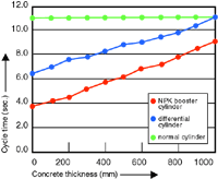
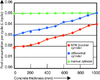
In the figures below an example is given of a S-23XCR.
Figure 1 shows the cycle time for several concrete thicknesses.
One cycle time is time for opening plus time for closing. It is clear
that the NPK Powerbooster is much quicker than a normal cylinder.
Figure 2 shows the fuel consumption for each cycle of breaking.
Compared to a normal cylinder the NPK Powerbooster cylinder
consumes 40% less fuel, at 600 mm thickness!
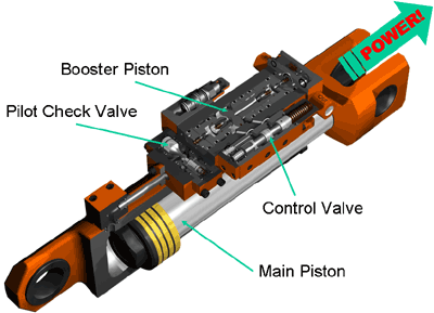
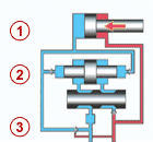
Schema of PowerBooster
PowerBooster step by step
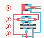 Jaw closing, no resistance: high speed
- Excavator: 250 bar
- Booster inactive
- Control valve
- Sequence valve closed
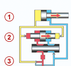 Jaws meet resistance: booster activated
- Booster moves to right, pressure 850 bar!
- Control valve lets oil flow to booster
- Sequence valve opened
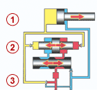 Resistance remains: high break-out force
- Booster works two ways high pressure remains!
- Control valve operates booster continuesly
- Sequence valve remains open
- Booster inactive no increase of pressure
- Control valve in start position
- Sequence valve opened

